Vortex Shedding Calculator
(beam vibration frequency)
Natural Frequency

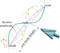
Fig 1. Excited Mode Shape
Once its natural frequency (see Mode Shapes technical help page) has been reached, continued exposure of a structure or its elements to a matching external force that exceeds excitation requirements will continue to increase its deflections (dynamic amplitude; Fig 1) ultimately leading to structural failure or premature fatigue.
The mode shape of a vibrating beam (see Fig 1) is the shape of the 'wave' between 'nodes' and is generally quoted as its amplitude. As long as the beam is vibrating at a frequency that is not close to 'natural' (see Output Data, 1) below) the situation will not worsen with continued exposure to the conditions creating it.
Vortex Shedding
In 'the industry', Vortex shedding is the term used to describe the fluctuating motion of a beam or structure due to fluid passing across it or along it at a velocity that could create the above condition. This is not an exact science and the work done to date by Strouhal, Keulegan, Carpenter, Sarpkaya etc. should be considered as useful guidance only, it is always better to minimise the chances for such events by design (guides not clamps, minimise free-span lengths, keep supports away from nodal positions, maximise/vary sectional dimensions, etc.).
As can be seen in Fig 1, adjacent modes in a multi-mode configuration will rotate 180° out of sync with each other ('action equals reaction'). And as the dominant force switches between horizontal and vertical around the cycle (❶→❷→❸→❹), it will not vibrate in a single plane but follow an elliptical path. This will of course have the effect of inducing rotary forces similar to those in cycle pedals, the effect of which can be seen in the destruction of the Tacoma narrows bridge (1940) from the effects of vortex shedding. The things you can do to minimise its likelihood include providing suitable supports (see Supports below), break up smooth & consistent surfaces, and vary the shape coefficients along the length of constant section structures.
As it is necessary for consistent conditions along the entire length of a sufficiently long and susceptible beam for vortex shedding to occur, vertically mounted structures rarely suffer from this phenomenon as gravity is not a contributor, tensions and velocities vary along their length and long structural elements mounted vertically should use guides not clamps.
Supports
A Clamped support effectively prevents all rotational and directional movement in the beam at the support (a Clamp). This type of support is most likely to allow natural frequency vibrations to become excited and therefore expose the beam to potential damage or reduce fatigue life.

A Pinned support prevents only lateral, directional movement in the beam. All other movement (rotation and axial) is permitted (a Guide). This type of support is less likely to allow natural frequency excitation to occur.
Selecting and positioning your supports is crucial to eliminating the opportunity for vortex shedding. As shown in Fig 2 there are good and bad support locations. You should always make sure that your supports are as far away from potential nodes as possible.
Oscillating Force
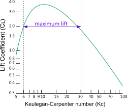
The horizontal component of the amplitude is generated by the drag force (Fᴄᴅ Fig 1) induced by the fluid. The lift coefficient can be estimated using the graph presented by Sarpkaya (Fig 5) and the consequent lift force (Fʟ Fig 1) represents the vertical component of the amplitude. Together these forces (Fₒ Fig 1) define the dynamic amplitude and the ability for the mode to continue oscillating at its natural frequency.
The oscillation force (Fₒ Fig 1) calculated in Vortex Shedding is not required for the entire cycle, elasticity, inertia and gravity carry the mode through most of it (gravity helping the downward stroke only though!). The inertia generated between ❶→❷ (see Fig 1) needs to be sufficient to assist the mode against fluid flow, around the remaining three-quarters of the cycle (❷→❶). During this part of the cycle (❶→❷), elasticity and gravity are working against mode-motion and much of the inertia will have been dispersed. However, as forces F₁ and F₂ are required to generate the amplitude alone, it is considered reasonable that the fluid force alone must at least be capable of deflecting the mode between ❶→❷ with little additional assistance.
It is also reasonable to conclude, however, that at its 'natural frequency', there will be some surplus inertia left to keep the process going. And given that this is not an exact science and that factors such as Cd, Ca, Cʟ, etc. are subject to change (even during a single cycle), there is little point in accurately calculating the remaining inertia at ❶ and resolving the cyclic forces through to ❷ in order to establish the exact force required to generate the energy to cycle the mode back around to ❶ again. CalQlata has therefore deemed it reasonable to claim that….

Fig 3. Two Beam Modes
"If Fₒ is close to or higher than F₁ or F₂, there will be sufficient capacity to excite the mode concerned into greater amplification and, that excitation is unlikely if there is significantly less capacity in Fₒ"
Important: The above statement has greater relevance in water where losses during the cycle are higher, and greater capacity is required in Fₒ to continue cyclic regeneration. In air, less capacity is required in Fₒ to generate sufficient impetus to take the mode back to ❶ again.
Fatigue
Fatigue life is almost always a potential problem for any vibrating structure (see Fatigue technical help page).
By using M₁ & M₂ in CalQlata's Beams or Pipe and Combined Stress to find a stress range (using Principal stresses) in the beam (or structure) that together with the number of vibration cycles expected during its life you will have generated one of the stress blocks for the structure's fatigue calculations.
Vortex Shedding Calculator - Technical Help
Units
You may use any units you like, but you must be consistent.
Building Your Beam
CalQlata's Mode Shapes calculates the properties of an unsupported vibrating beam, defining each mode type in its dynamic configuration. There are only three probable mode types and no single vibrating beam will have more than two between adjacent supports:
clamped-clamped: only occurs with a single 1-Mode clamped-clamped configuration
clamped-pinned: only occurs at both ends of a clamped-clamped beam with more than one mode or one end of any vibrating clamped-pinned beam
pinned-pinned: covers all the other probable modes
Vortex Shedding does not calculate the vortex shedding characteristics of a beam (unless it is a single mode configuration). It calculates the likelihood of either one of two modes achieving natural frequency along with the dynamic properties of both. You may enter their properties manually or you can import the relevant data from Mode Shapes
You build your beam up by adding the mode lengths together as follows:
If you have a 6 mode 'Clamped-Pinned' configuration you know that you must add the modal lengths together to create the full length. You also know (see above) that you have one clamped-pinned end and all the rest are 'pinned-pinned', i.e. the other end is the same mode configuration as the middle modes.
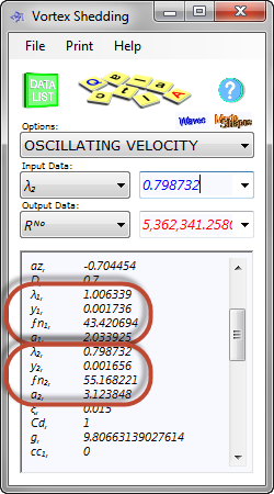
Therefore, you add; 1 times 1.006339 (λᴱᴺᴰ) to 5 times 0.798732 (λᴹᴵᴰ) for the total beam length of '5' (see Mode Shapes technical help page, Fig 4). You can then position all of your nodes and maximum deflections from either end.
Remember, maximum deflection always occurs in the middle of the mode for 'clamped-clamped' and 'pinned-pinned' ends and 0.4215 times λ from the pinned end of a 'clamped-pinned' mode.
Shape Coefficients

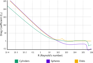
Fig 4. Drag Coefficient vs Reynolds Number
Lift, Drag and Added mass coefficients all contribute to the performance of a beam under vortex shedding conditions.
See Added Drag technical help page for a detailed description of these coefficients.
The drag coefficient varies linearly with the Reynolds number up to about 100 (Fig 4), after which it remains constant at about 1.0 plus or minus 0.5 dependent upon local conditions
As most practical applications involve a Reynolds number of more than 100,000 the drag coefficient can be calculated using factors between 0.7 and 1.5 (see CalQlata's Added Drag calculator).
The drag force (Fᴄᴅ) pushes the mode(s) in the direction of the fluid movement (see Fig 1). This has the effect of shifting the structural element forwards along its entire length.
Lift CoefficientThe lift coefficient (Cʟ), which is directly related to the Keulegan-Carpenter number (Kc), creates the force (Fʟ) that pushes the mode upwards. Maximum lift conditions apply in the Kc range 6 to 30 (see Fig 5). You will notice (in your calculations) that this value changes stepwise with the Strouhal number (Sᴺᵒ) in the constant velocity calculation option, and also in the oscillating flow calculations where Kc exceeds 30.
Added Mass Coefficient
Fig 5. Lift Coefficient vs
Keulegan-Carpenter number
It is important that you include the added mass and fluid (content) components in the mass (mₑ) value entered for the structural member. This can be done manually or you can use CalQlata's Pipe calculator.
Input Data
Vortex Shedding does not calculate the properties of a beam at its natural frequency, you will need to do this yourself and then enter the values in this calculator or you can use CalQlata's Mode Shapes and import the data into Vortex Shedding automatically. The same applies to the water particle velocities, which you can calculate and enter yourself or CalQlata's Waves (ocean) can do this automatically for you. If you use Waves (ocean) (or any other calculator) to calculate water particle velocities, unless you have special reasons for doing otherwise, don't forget to maximise your horizontal velocities (the dominant cycling force) by setting the position through the wave cycle to zero (degrees).
If you have only one mode to address and you have not installed Mode Shapes then simply enter the data for the mode for which you have the data leaving empty any data entry slots with a '₂' suffix.
Output Data
Bending moment (M) is calculated using the mode length (λ) and cycling force (Fₒ) plus effective mass per unit length (mₑ) as the worst case condition during any one cycle. Whilst it is not strictly correct, you may use twice the largest of M₁ or M₂ to define a stress range for a fatigue stress-block (see Notes at the foot of this page).
If the 'reduced velocity' (vr) falls within a particular range, the ability to resonate will exist, and you will be notified through the following results: VI₁, VI₂ (probability of in-line vortex shedding) and VC₁, VC₂ (probability of cross flow vortex shedding)
It is then necessary to verify;
1) that the ratio of the vortex frequency of the fluid and the natural frequency of either mode (ƒₒ/ƒⁿ₁ or ƒₒ/ƒⁿ₂) is between 0.9 and 1.1, and;
2) that the fluid force is sufficient to accelerate the structural element through the fluid at the natural frequency (Fₒ ≥ F₁ or F₂ - see Oscillating Force above).
If all these conditions apply, there is an excellent chance that vortex shedding will occur in the structure at some time during its life and you should do something about it (see Vortex Shedding above).
The stability parameter (ζ) is calculated for information only giving you the opportunity to determine amplification using the formula; A = 0.31 x γ x D x (0.062 + 0.077 x ζ²)½ if you prefer (γ is calculated in CalQlata's Mode Shapes).
Data Import
Vortex Shedding provides a data import facility for you to extract information from two other 'export' calculators (Waves (ocean) and Mode Shapes) if they have been installed.
The information retrieved from Waves (ocean) is the current velocity (vc), vertical and horizontal wave particle velocities (vx & vz), wave particle accelerations (ax & az) and acceleration due to gravity (g).
The information retrieved from Mode Shapes is mass per unit length (mₑ), dimension (D), mode wavelength (λ₁ & λ₂), mode static deflection (y₁ & y₂), mode natural frequency (ƒⁿ₁ & ƒⁿ₂), acceleration necessary to generate natural frequency (a₁ & a₂), the damping ratio (ξ) and the special end condition clamped-clamped with only one mode (cc₁).
If you need to change any of the above values, then you should do so after importing from the associated Data File.
Important: You should not forget to save the calculation data in the export calculators before trying to import it into Vortex Shedding.
Notes
- Vortex shedding is not an exact science. It is a probability of occurrence.
- You never use maximum values in probability calculations, you use the most probable.
- As such, you will select a 'most probable' wave and/or current condition to define your stress block frequency.
- Therefore, the slightly conservative stress range from using 2 times M will compensate for the more aggressive hydrodynamic conditions in the associated stress block.
- As the less aggressive hydrodynamic conditions are not considered, your results will be slightly conservative.
Further Reading
You will find further reading on this subject in reference publications(3, 6 & 12)

