Anchor

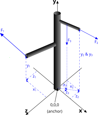
Fig 1. A Post or Staff with Multiple Loads
An anchor is any fixing that remains immovable.
In all cases, an anchor is assumed (by CalQlata) to be stationary at the time a load is applied, including an anchor that may occasionally relocate.
In this case, a single anchor located at co-ordinate 0,0,0 is subjected to multiple (up to 10) loads applied at various locations relative to the anchor. An anchor may be the fixing for a post or staff with a single load, or branches with additional loads (Fig 1), or a structure that is affixed to a foundation or vessel deck via a central base, to which a number of peripheral loads may be applied.
For a single load applied to multiple fixings (anchors), please use CalQlata's Anchors calculator.
Each individual applied load will induce a force and a moment about the anchor, that can be resolved into force vectors 'Fx, Fy, Fz' and moments 'Mx, My, Mz'. Where multiple forces are applied, they may be combined into a single equivalent force and moment and thereafter similarly resolved into force vectors 'Fx, Fy, Fz' and moments 'Mx, My, Mz'.
Structural or deck strength may then be established from these force vectors and moments.

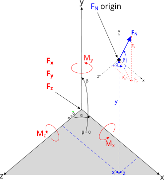
Fig 2. Co-ordinate System 'y'
Anchor Calculator – Technical Help
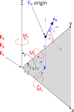
The most popular co-ordinate systems are either where the y-axis points vertically upwards Fig 2, or where the z-axis points vertically upwards (Fig 3).
In both cases, the forces and moments at the origin (0,0,0) will be identical, but the input and output designations will differ.
In Anchor, you may enter your input data using either system, you simply need to be careful with your directions and angles.
Irrespective of the system used, Anchor will reorientate the input data when switching between options.
Units
You may use any units you like, but you should be consistent; remember you will only get out whatever you put in.
Metric and Imperial units are provided {metric, Imperial} below for information only.
Input Data

Fig 3. Co-ordinate System 'z'
The following input data applies to, and is repeated for, each applied load; 1 to 10:
F (force): The applied load {N, lb}
α (angle): The angle of rotation about the vertical axis ('y' or 'z') {°}
β (angle): The vertical angle of rotation from the horizontal plane ('x,z' or 'x,y') {°}
x (distance): The distance to origin of 'F' in direction 'x' from co-ordinate 0,0,0 {m, ft}
y (distance): The distance to origin of 'F' in direction 'y' from co-ordinate 0,0,0 {m, ft}
z (distance): The distance to origin of 'F' in direction 'z' from co-ordinate 0,0,0 {m, ft}
Output Data
The following output data is the solution from all of the input data combined and resolved into ...
... the total force in the anchor at co-ordinate 0,0,0:
Fx (force): in direction 'x' {N, lb}
Fy (force): in direction 'y' {N, lb}
Fz (force): in direction 'z' {N, lb}
... the total moment in the anchor at co-ordinate 0,0,0:
Mx (moment): about the 'x-axis' {N.m, lb.ft}
My (moment): about the 'y-axis' {N.m, lb.ft}
Mz (moment): about the 'z-axis' {N.m, lb.ft}
Applicability
This calculator applies to any single anchor to which one or more individual loads are applied. The single anchor may be any size or shape, but the output data will be valid at the centre of the base's second moment of area. See also CalQlata's Anchors calculator.
Accuracy
The output data from this calculator is as accurate as the input data.
Further Reading
You will find further reading on this subject in reference publications(3 & 12)

