Vessel Motion Calculator
(displacements velocities accelerations)

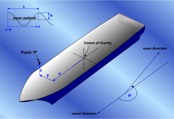
Fig 1. Motions of Point 'P' Relative to Vessel CofG
A vessel (e.g. ship) floating on the surface of an undulating sea will move (shift and rock) according to its transfer functions (see Response Amplitude Operators below) and the properties of the passing wave.
It is important to know how much and how quickly a vessel will move because the resultant velocities and accelerations anywhere in its structure (e.g. point 'P' Fig 1) will affect loading conditions for which, structural components, handling equipment and seafastenings must be designed.
There are many ways to calculate the expected movement of a ship such as, fluid damping, potential, simple (trigonometric) harmonics, rules and regulations, etc. However, no matter how complex the theory used, it is only as accurate as the wave sequences applied to the calculations. And the chances that the actual and anticipated seastates are coincident, or even similar, are very small. Any deviation from the design seastate will result in motions different to those predicted in theory, and the heavier the seas, the greater the deviation probability.
This is why the shipping authorities do not rely on classical theories for the classification and certification of ships and their seafastenings. The most authoritative certification bodies around the world, such as DnV, Lloyds and ABS, have collected sufficient historical data and employ sufficiently experienced engineers to be able to apply suitable load factors that accommodate most conditions expected in our oceans. However, it would be uneconomic and impractical to manufacture equipment suitable for use in offshore operations such as oilfield installation, fishing, construction, etc. using these rules.
Offshore operations are almost always performed during periods of light seas (such as late, spring, summer and early autumn) and within known weather windows. Therefore, more accurate vessel accelerations for these conditions are usually preferred in order to optimise operating equipment with regard to cost and size. Classical theories are much more appropriate for such applications given the improved predictability of light seastates.

Fig 2. RAO Phase Angle
Vessel Motions
The degree to which a floating vessel will move due to a passing wave is dependent upon its transfer functions (RAOs), which are defined by its physical properties (shape, mass, buoyancy, etc.) but primarily by its metacentric height. Along with each transfer function, there is an associated phase angle (Fig 2) that defines how long before or after the maximum amplitude of a wave passing the centre of gravity of the vessel that the transfer function reaches its peak.
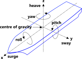
A vessel's motions are defined and measured in six degrees of freedom (Fig 3), all of which; angular (rotary) and linear, are mathematically combined to provide the three linear accelerations (x, y and z) used in design calculations.
It is preferable to keep accelerations and velocities as low as possible in order to minimise loads on vessel parts and transported masses.

Fig 3. Vessel 6-Degrees of Movement
Response Amplitude Operators (RAO)
Response amplitude operators is a term used collectively for the transfer functions and their associated phase angles, each of which applies to the respective movement of a vessel's centre of gravity for a given wave period and direction. You simply multiply the transfer function by the wave amplitude to find the associated movement.
The RAOs provided for the calculation of displacements, velocities and accelerations are normally issued in the following format for each wave period and direction:
| Wave period and direction | Surge {m/m} |
Sway {m/m} |
Heave {m/m} |
Roll {°/m} |
Pitch {°/m} |
Yaw {°/m} |
|---|---|---|---|---|---|---|
| Transfer Function | x | y | z | R | P | Y |
| Phase Angle (°) | αx | αy | αz | αR | αP | αY |
Note: Angles can be provided in degrees or radians
Every vessel is provided with its table of RAOs that define its performance characteristics and these values are normally used in classical theory design and operational calculations.
See CalQlata's Vessel RAOs calculator
Classical Theory
The classical theory used in CalQlata's vessel accelerations calculator is based upon the trigonometric projection of a point located at a specified position on the vessel relative to its centre of gravity, which identifies the simple harmonic movement of that point generated by the vessel's transfer functions.

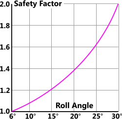
Fig 4. Design Safety Factors
Whilst this theory is ideally suited for deep-water waves of moderate amplitude that induce roll angles of up to 6°, it can also be used for design calculations associated with roll angles greater than this if you apply a suitable safety factor to your design calculations. The reason why safety factors should be used for larger expected roll angles is not because the theory is less accurate at larger roll angles; it is simply because the predictability of design seastates becomes less reliable with increased wave amplitude.
Fig 4 shows a safety-factor/roll angle relationship that may be used for design calculations that involve roll angles greater than 6°.
DnV Rules for Ships (January 2012)
DnV's rules for ships are not significantly different from those issued by Lloyds and ABS in terms of philosophy and method. However, if you are designing within the certification and or classification rules of either Lloyds or ABS, you should be using their calculation methods.
The philosophy behind vessel motions calculated using the rules of any certification authority is that they apply factors to standard formulas that will produce accelerations suited to conditions they expect in transit according to their extensive knowledge and experience.
That is, you can design your seafastenings according to these rules and be fully confident that they will remain in place and secure throughout the journey.
It would not be appropriate to use these rules to calculate the expected loading conditions on equipment and facilities for offshore operations as the resultant dimensions would be impractically large. Therefore, if your requirement is for offshore operations, you should use the Classical Theory (above).
The vessel accelerations calculator provides values for the various factors used in this calculation option.
Vessel Accelerations - Technical Help
Because of the complexity and the amount of input data required for both calculation options, the vessel acceleration calculator remembers all the input data for both calculation options ('Classical Harmonic' and 'DnV Rules for Ships') as you switch between them. Vessacc also saves all the input data for both calculation options into its Data File. However, it only saves the output data into the Data File for the calculation option active at the time of saving.
Please remember when uploading RAs from the RAO calculator that they apply only to the wave and the angle through it as entered in RAO. Each time you alter vessel heading, angle-through-wave and/or wave conditions, the RAs must be recalculated and uploaded.
Don't forget to save the calculated data in RAO before importing it into Vessac.
Classical Harmonic calculation option
Angles are always entered and provided in degrees (°) and time in seconds (s). Length units can be anything you like as long as you are consistent.
The input data is organised and specified as follows:
'Longitudinal co-ord' (x), 'latitudinal co-ord' (y) and 'vertical co-ord' (z) are the co-ordinates (distances) from the vessel's centre of gravity to a point 'P' anywhere on or within it, for which you wish to know the displacement, velocities and accelerations.
Frictional Phase Angles (xᴾᴴ, yᴾᴴ & Yᴾᴴ)
You will notice that these values remain unaltered after importing data from the RAO calculator. This is because RAO only calculates the geometric response amplitudes, not the frictional values, which must be entered manually in Vessac.
Therefore, whilst values calculated in Vessac for surge, sway and yaw at point 'p' are correct irrespective of the frictional phase-angle entered; the coincident CofG values will not be correct if incorrect frictional phase angles have been entered. This is because the phase-angles at CofG and 'p' will be different at the same instant in time. And because such disparity is normally most significant along vessel length, surge-calculations are where greatest discrepancy will be observed.
An approximate frictional phase angle can be found simply by modifying the appropriate value until the displacements at 'p' and CofG match. But remember; frictional phase-angles are always negative (lagging) and in surge calculations can be around 90° if μ is close to 0° or 180°.
Alternatively, the correct value may be found for a frictional phase angle by applying 3D-Pythagoras theorem to the RA anglar displacements (Rᴳ, Pᴳ & Yᴳ) to obtain the expected difference between values (e.g. surge; xᴳ & sᵤᴾ).
Version 1.0 Uses Response Amplitude Operators so vessel and wave details are required for analysis (Fig 1).
Vessel speed (v) is the straight line velocity of the vessel through a wave at any heading (angle).
Wave amplitude (η) is the height of the surface of the water above mean sea level at 'θ'.
Encounter wave length (Lₑ) at the vessel's heading, encounter angular wave velocity (ωₑ)at the vessel's heading, angle through wave (θ), wave number (k) and wave celerity (c) are all properties of the wave passing below the vessel.
Note: the 'encounter' values may be calculated as follows
(where μ = vessel heading {angle} & L = wave length):
Lₑ = L ÷ Cos(μ)
ωₑ = 2π(c - v.Cos{μ}) ÷ L
Response Amplitude Operators: surge RAO (xᴿᴬᴼ), surge phase angle (xᴾᴴ), Roll RAO (Rᴿᴬᴼ), Roll phase angle (Rᴾᴴ), sway RAO (yᴿᴬᴼ), sway phase angle (yᴾᴴ), Pitch RAO (Pᴿᴬᴼ), Pitch phase angle (Pᴾᴴ), heave RAO (zᴿᴬᴼ), heave phase angle (zᴾᴴ), Yaw RAO (Yᴿᴬᴼ) and Yaw phase angle (Yᴾᴴ) are the response amplitude operators and phase angles for the vessel at the appropriate wave period and entered wave direction (μ).
Unit lengths; m, ft, yds, etc., angles; in degrees [°] and degrees per unit length [e.g. °/m]
Version 1.1 & 1.2: Uses Response Amplitudes (not Response Amplitude Operators), therefore the encountered angular velocity (ωₑ) of the vessel (at its heading), i.e. the speed with which the RAs are energised is alone responsible for the velocities and accelerations at a vessel's CofG and at point 'p' (Fig 1).
Also included is the vessel wave encounter period (pe), the angle through the wave (θ) and the wave profile height (η), which is encountered at angle 'θ'.
Response Amplitudes: surge RA (xᴿᴬ), surge phase angle (xᴾᴴ), Roll RA (Rᴿᴬ), Roll phase angle (Rᴾᴴ), sway RA (yᴿᴬ), sway phase angle (yᴾᴴ), Pitch RA (Pᴿᴬ), Pitch phase angle (Pᴾᴴ), heave RA {m} (zᴿᴬ), heave phase angle (zᴾᴴ), Yaw RA (Yᴿᴬ) and Yaw phase angle (Yᴾᴴ) are the response amplitude operators and phase angles for the vessel at the appropriate wave period and entered wave direction (μ).
Unit lengths; m, ft, yds, etc., angles; degrees [°]
The output data is organised and specified as follows:
The output data has been divided up as follows:
Linear displacement of CofG: surge (xᴳ), sway (yᴳ) and heave (zᴳ)
Linear velocity of CofG: surge (ẋᴳ), sway (ẏᴳ) and heave (żᴳ)
Linear acceleration of CofG: surge (ẍᴳ), sway (ÿᴳ) and heave (z̈ᴳ)
Rotary displacement of CofG: roll (Rᴳ), pitch (Pᴳ) and yaw (Yᴳ)
Rotary velocity of CofG:, roll (Ṙᴳ), pitch (Ṗᴳ) and yaw (Ẏᴳ)
Rotary acceleration of CofG: roll (R̈ᴳ), pitch (P̈ᴳ) and yaw (Ÿᴳ)
Linear displacement of point 'P': surge (sᵤᴾ), sway (sᴾ) and heave (hᴾ)
Linear velocity of point 'P': surge (ṡᵤᴾ), sway (ṡᴾ) and heave (ḣᴾ)
Linear acceleration of point 'P': surge (s̈ᵤᴾ), sway (s̈ᴾ) and heave (ḧᴾ)
These are the values to be used in your design calculations.
Wave elevation @ CofG (Wᴱ)
Version 1.1 only: Wave and RA input data may be calculated and/or imported from CalQlata's Vessel RAOs caculator of the same version if it has been installed on the same computer.
Version 1.2 only: RA input data may be calculated and/or imported from CalQlata's RAO calculator if it has been installed on the same computer.
Note: Displacements, velocities and accelerations are symbolised by their derivatives; e.g. x, ẋ and ẍ respectively in order to make property recognition easier.
Heave (zᴳ)
You may notice a difference between heave at a vessel's CofG as calculated in CalQlata's RAO calculator and in Vessacc (RAO; zᴿᴬ & Vessacc; zᴳ).
This will be due to the added mass value entered for heave ('ADDED MASS COEFFICIENT (Ca)') in the Data File of the RAO calculator. Note: the calculations in Vessacc are simple harmonic whilst RAO's calculations include the effects of damping, spring-coefficient and added mass.
To match these values you need to iterate your 'Ca' value for heave in RAO and recalculate until these two values (RAO; zᴿᴬ & Vessacc; zᴳ) match. Very small changes in 'Ca' (e.g. 1 to 1.015) can generate significant variations in 'zᴿᴬ'
DnV Rules for Ships calculation option
All units must be as given in the vessel accelerations calculator.
The input data is organised and specified as follows:
'longitudinal dimension' (x), 'latitudinal dimension' (y) and 'dimension' (z) are the dimensions (distances) from the vessel's aft perpendicular, its centre of gravity and its baseline (respectively) to a point 'P' anywhere on or within the vessel for which you need the motions.
'vessel velocity' (v) is the velocity of the vessel (in knots).
'vessel length' (L), 'vessel beam' (B), 'vessel height' (D), 'vessel draught' (T), are the overall dimensions of the vessel's waterline, except for the length (L) which is the distance between the fore and aft perpendiculars or 96% of the longitudinal waterline.
displacement (Δ) is the displacement of the vessel.
metacentric height factor (GMᶠ), damping factor (k), roll acceleration factor (kᵣ) and restricted service reduction (Sᴿ) are factors advised by DnV for each associated function. These factors are quantified in the vessel acceleration calculator.
The output data has been divided up as follows:
common acceleration parameter (ao) is a parameter used in the following results
period of roll (Tr) and period of pitch (Tp) are the periods of roll and pitch of the ship
angle of roll (R), angle of pitch (P), are the angles of roll and pitch of the ship
surge acceleration (ax), sway-yaw acceleration (ay) and heave acceleration (az) are accelerations at point 'P' as indicated
tangential roll acceleration (atr) and tangential pitch acceleration (atp) are the tangential accelerations at point 'P' due to roll and pitch
vertical roll acceleration (avr) and vertical pitch acceleration (avp) are the vertical accelerations at point 'P' due to roll and pitch
vertical acceleration (av), transverse acceleration (at) and longitudinal acceleration (al) are the combined linear vertical, transverse and longitudinal accelerations at point 'P'. These are the values to be used in your design calculations.
Application of Accelerations
In order to find a load in any direction (x, y or z) you simply multiply the mass by the acceleration in that direction.
Or you can apply Pythagoras' theorem: a = ( av² x at² x al² )½ to define the combined acceleration and multiply the resultant acceleration (a) by the mass.
Applicability
Calculation option 'Classical Harmonic' is applicable to deep-water, rolling (not breaking) waves that induce vessel roll of less than 6° (see Classical Theory above)
Calculation option 'DnV Rules for Ships' is applicable to any vessel in transit conditions (see DnV Rules for Ships above)
Accuracy
Calculation option 'Classical Harmonic' is 100% accurate for sinusoidal waves of any size and condition. The accuracy limitations associated with this calculation option are due to the inability to predict heavy seastates.
Calculation option 'DnV Rules for Ships' is as accurate as required by DnV for the classification of their ships including all necessary safety margins and factors. It does not purport to provide an accurate representation of vessel accelerations at any time during transit.
Further Reading
You will find further reading on this subject in reference publications(6, 8, 42 & 43)

