Shock Load Calculator

Fig 1. Drive a Nail into Wood
A shock load (or force) is variously described as: "a dynamically applied load greater than double the static load", "when the duration of the impact is greater than half the natural period of the member", "the transmission of kinetic energy to a system over a relatively short period when compared to the system's natural period", "a suddenly applied load", etc.
In reality any dynamically applied load can be regarded as a shock with varying degrees of intensity.
For example:
1) A load very slowly applied will result in a force only slightly greater than the equivalent static force, but is a shock load nonetheless
2) A load applied to a system of sufficient flexibility to reduce the load's deceleration close to gravitational acceleration will be marginally greater than the equivalent static force, but is also a shock load
3) The impact between a mass and a system neither of which deflect at all will result in a shock load of infinite magnitude irrespective of the impact velocity or the magnitude of the mass
Shock loads can be a useful resource when applied correctly and in a controlled manner, such as in pile or nail driving and panel beating whereby a relatively small mass can be transformed into a relatively high impact or driving force. For example: driving a nail into a piece of wood…
Nail Driving
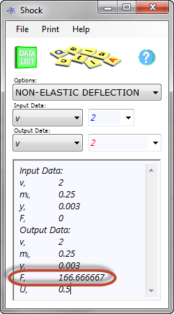
If you hit your nail with your 0.25kg hammer-head at 2m/s and it embeds the nail 4mm into the wood...
As can be seen in Fig 1, the force ('F') produced is 166.7N (≡17kg). This means that a small hammer has produced an effective load 68 times greater than its mass.
If your nail is 30mm long and half of it is hammered into the wood, the other half representing the thickness of the body you are trying to secure, the theoretical holding power of the nail will be 5 times 17kg (85kg). In practice, however, hammering a nail into a piece of wood tends to weaken the joint and you will probably retain only half of this theoretical capacity. Nevertheless, a hammer weighing only 0.25kg has managed to apply a holding force of over 40kg without a great deal of effort.
Deformation Under Impact
When protecting an object from the damaging effect of shock loads, it is always a good idea to ensure that it has sufficient capacity to deflect under impact. The more it can deflect the more kinetic energy will be dissipated during impact and the lower will be the resultant force.
The deflection absorbed during impact occurs in both the impacting mass and the system. Therefore, if an impacting mass deforms 1mm and the impacted system deforms 5mm, the total deflection is 6mm.

Fig 2. Point Load
Whilst you can account for deflection response in an impacting mass when designing under known conditions, in most cases the impact is accidental and the properties of the impacting mass are unknown. As it is necessary to design for worst case scenarios when considering accidental events, except under special or predictable circumstances, the impacting mass is normally assumed to be rigid (i.e. zero deflection) and the only deflection considered in the calculation comes from the impacted system.
Shock Load Calculator - Technical Help
The shock load calculator automatically assumes the mass impacts at the worst possible position generating highest possible bending moment and hence greatest stress.
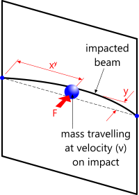
When designing a typical beam (Fig 2) or plate for possible impact, its ability to survive is usually based upon a combination of the permissible deflection and its structural strength.
BEAMS – Point Load
In the following calculation a tubular transom (THS 26.9x4) fails as a result of a collision with a 2kg mass travelling at less than 4.2m/s at the moment of impact:
| Input Data: | (Supports: Fixed-Fixed) |
| impact velocity (v) | 4.188294 {m/s} |
| impacting object mass (mᵢ) | 2 {kg} |
| gravitational acceleration (g) | 9.80663139027614 {m/s²} |
| beam mass (m/L) | 2.258994 {kg/m} THS 26.9x4 made from steel |
| beam depth (d) | 0.0269 {m} outside diameter of THS 26.9x4 |
| beam length (L) | 1 {m} |
| Young's modulus of beam (E) | 207000000000 {N/m²} Young's modulus for steel |
| second beam moment of area (I) | 1.9439215479E-08 {m⁴} |
| Output Data: | |
| force (F) | 3,681.394114 {N} ...of the impact |
| deflection (y) | 0.004765 {m} impacted plate |
| natural frequency (ƒⁿ) | 9.21947 {Hz} |
| natural period (tⁿ) | 0.054233 {s} |
| impact duration (t) | 0.002275 {s} |
| factor (K) | 187.699219 {} mass amplification factor |
| energy dissipated (U) | 17.541807 {N.m} |
| maximum plate stress (σ) | 3.1839473E+008 {N/m²} bending |
| distance to y (xʸ) | 0.5 {m} position of maximum deflection |
| distance to σ (xˢ) | 1 {m} position of maximum stress |
The maximum calculated bending stress (σ) in the above transom as a result of the applied load is greater than the expected minimum yield strength for structural steel.
To correct this condition we need to increase the strength of the transom; e.g. THS 42.4x2.6:
| Input Data: | (Supports: Fixed-Fixed) |
| impact velocity (v) | 4.188294 {m/s} |
| impacting object mass (mᵢ) | 2 {kg} |
| gravitational acceleration (g) | 9.80663139027614 {m/s²} |
| beam mass (m/L) | 2.551972 {kg/m} THS 42.4x2.6 made from steel |
| beam depth (d) | 0.0424 {m} outside diameter of THS 26.9x4 |
| beam length (L) | 1 {m} |
| Young's modulus of beam (E) | 207000000000 {N/m²} Young's modulus for steel |
| second beam moment of area (I) | 6.46445E-08 {m⁴} |
| Output Data: | |
| force (F) | 6,713.341458 {N} ...of the impact |
| deflection (y) | 0.002613 {m} impacted plate |
| natural frequency (ƒⁿ) | 12.449994 {Hz} |
| natural period (tⁿ) | 0.040161 {s} |
| impact duration (t) | 0.001248 {s} |
| factor (K) | 342.285806 {} mass amplification factor |
| energy dissipated (U) | 17.541807 {N.m} |
| maximum plate stress (σ) | 2.7520292E+008 {N/m²} bending |
| distance to y (xʸ) | 0.5 {m} poisition of maximum deflection |
| distance to σ (xˢ) | 1 {m} position of maximum stress |

Fig 3. Distributed load
The modified transom is less than 13% heavier but more than a 13% stronger lowering maximum bending stress to an acceptable level.
You will notice that whilst the impact force ('F') has increased due to reduced deflection ('y'), there is sufficient increased structural strength in the second moment of area of the new transom to lessen the resultant bending stress.
BEAMS – Distributed Load
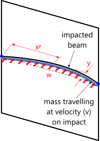
Immerse the above transom (THS 26.9x4) into the sea (Fig 3) 10 metres below the surface to see what happens when a 6 metre x 12 second wave hits it with a coincident 3m/s current. Using CalQlata's Waves, Added Drag and Fluid Forces calculators we can identify an horizontal force per unit length of 2,434.227464N/m for this wave. The shock load calculator, however, requires this value to be entered as an equivalent impacting mass per unit length:
See the bottom of the page for a proposed conversion procedure⁽¹⁾
| Input Data: | (Supports: Fixed-Fixed) ⁽⁴⁾ |
| impact velocity (v) | 4.188294 {m/s} |
| impacting object mass (mᵢ/L) | 0.437222157 {kg} |
| gravitational acceleration (g) | 9.80663139027614 {m/s²} |
| beam mass (m/L) | 2.258994 {kg/m} THS 26.9x4 made from steel |
| beam depth (d) | 0.0269 {m} outside diameter of THS 26.9x4 |
| beam length (L) | 1 {m} |
| Young's modulus of beam (E) | 207000000000 {N/m²} Young's modulus for steel |
| second beam moment of area (I) | 1.9439215479E-08 {m⁴} |
| Output Data: | |
| force (F) | 2,434.239033 {N} ...of the impact |
| deflection (y) | 0.001575 {m} impacted plate |
| natural frequency (ƒⁿ) | 16.034127 {Hz} |
| natural period (tⁿ) | 0.031183 {s} |
| impact duration (t) | 0.000752 {s} |
| factor (K) | 567.729169 {} mass amplification factor |
| energy dissipated (U) | 3.834833 {N.m} |
| maximum plate stress (σ) | 1.4035435E+008 {N/m²} bending |
| distance to y (xʸ) | 0.5 {m} poisition of maximum deflection |
| distance to σ (xˢ) | 1 {m} position of maximum stress |
The above transom survives this load case as the resultant bending stress (σ≈140MPa) is well below the expected minimum specified yield for structural steel.
PLATES – Point Load
The load in this calculation is applied at its centre generating maximum bending moments and hence highest stress around the edge of a plate with fixed supports ('F') {highest stresses would occur in the middle of a plate with simple supports ('s')}.
A typical Shock calculation is shown below in which a 1.0m diameter x 20mm thick plate, fixed around its edge, is hit by a 10kg mass travelling at 10m/s on impact:
| Input Data: | (Supports: Fixed) |
| impact velocity (v) | 10 {m/s} |
| impacting object mass (mᵢ) | 10 {kg} |
| gravitational acceleration (g) | 9.80663139027614 {m/s²} |
| density of plate (ρ) | 7850 {kg/m³} steel |
| plate thickness (th) | 0.02 {m} |
| plate diameter (Øₒ) | 1 {m} |
| Young's modulus of plate (E) | 207000000000 {N/m²} Young's modulus for steel |
| Poisson's ratio of plate (ν) | 0.3 {} Poisson's ratio for steel |
| Output Data: | |
| force (F) | 123,472.082346 {N} ...of the impact |
| deflection (y) | 0.004049 {m} impacted plate |
| natural frequency (ƒⁿ) | 631.988595 {Hz} |
| natural period (tⁿ) | 0.001582 {s} |
| impact duration (t) | 0.00081 {s} |
| factor (K) | 1,259.067231 {} mass amplification factor |
| energy dissipated (U) | 500 {N.m} |
| maximum plate stress (σ) | 4.4215183E+007 {N/m²} bending |
As the resultant stress (σ) in the plate (≈44MPa) is extremely low for carbon steel, you could use a thinner plate or accommodate a greater impact force.
PLATES – Distributed Load
To see what happens if we immerse the above plate (Øₒ:1.0m x th:0.02m) 10m below the surface of the sea where it is impacted by a 20 metre x 14 second ocean wave and a coincident 3m/s current: Using CalQlata's Waves, Added Drag and Fluid Forces calculators we can identify a total horizontal force of 29,170.989508N for this wave on the plate, i.e. a surface a pressure of 37141.6574N/m². The shock load calculator, however, requires this value to be entered as an equivalent impacting mass per unit area:
See the bottom of the page for a proposed conversion procedure⁽¹⁾
| Input Data: | (Supports: Fixed) ⁽⁴⁾ |
| impact velocity (v) | 6.581083 {m/s} |
| impacting object mass (mᵢ/A) | 2.129428 {kg/m²} |
| gravitational acceleration (g) | 9.80663139027614 {m/s²} |
| density of plate (ρ) | 7850 {kg/m³} steel |
| plate thickness (th) | 0.02 {m} |
| plate diameter (Øₒ) | 1 {m} |
| Young's modulus of plate (E) | 207000000000 {N/m²} Young's modulus for steel |
| Poisson's ratio of plate (ν) | 0.3 {} Poisson's ratio for steel |
| Output Data: | |
| force (F) | 37,141.65737 {N} ...of the impact |
| deflection (y) | 0.001242 {m} impacted plate |
| natural frequency (ƒⁿ) | 309.178734 {Hz} |
| natural period (tⁿ) | 0.003234 {s} |
| impact duration (t) | 0.000377 {s} |
| factor (K) | 1,778.601379 {} mass amplification factor |
| energy dissipated (U) | 46.113442 {N.m} |
| maximum plate stress (σ) | 3.6576035E+007 {N/m²} bending |
The resultant stress is extremely low (<37MPa) and the plate deflects about than 1.24mm from a typical 1 year wave in the Atlantic Ocean, again you could use a thinner plate or accommodate a greater impact force.
NON-ELASTIC DEFLECTION
This calculation method can be used where you know three of the four variables and need to calculate the fourth, such as Nail Driving (see above).
'v' relative velocity of the impacting mass and should include the velocity of the impacted object if it is not stationary at the time of impact
'y' total deformation of the impacting mass and the impacted object

Fig 4. Plate: Point Load Calculation Check
'mᵒ' impacting mass only
'F' impact force
Definition
The definition of a shock load is sometimes described as a force that endures for less time than one half of the fundamental natural period (reciprocal of the natural frequency) of the impacted system. It is for this reason that the shock load calculator includes the natural frequency ('ƒⁿ'), the fundamental natural period ('tⁿ') and the duration ('t') of the calculated impact or shock load. However, this is simply one of many definitions and therefore provided for information only. CalQlata prefers to define a shock load as that which is subject to an acceleration greater than that due to gravity.
Factor
Factor 'K' essentially defines the number of times 'a' (acceleration) in the formula (F = M.a) is greater than 'g' (gravitational acceleration)
i.e. if K = 100 then the acceleration of the mass at the time of impact is 100 times greater than gravitational acceleration.
Checking
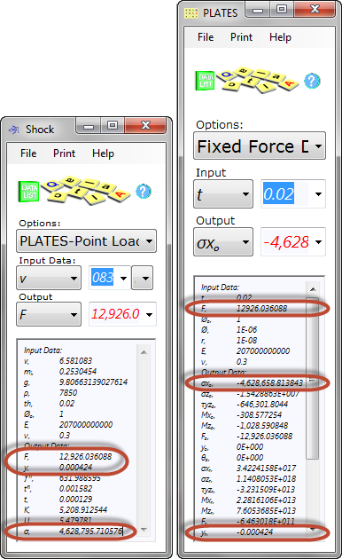
You may verify the results obtained in this calculator by checking the output data produced in the following calculators: Engineering Principles (Energy), Travelacc (Linear), Beams & Plates. You will need to be careful, however, to ensure that you are using the correct calculation option and loading conditions for such checks. An example verification calculation is provided in Fig 4 for a steel plate 1m diameter and 20mm thick impacted by a mass of 0.253kg at 6.581m/s using CalQlata's Plates calculator.
Units
You may use any units you like, but you must be consistent.
Accuracy
The accuracy of all calculations performed in the shock load calculator is as precise as the input data you enter.
Notes
- Converting wave force (F) into mass (mᵢ) for input into the Shock calculator you may use the formula;
m⁽²⁾ = 2.F⁽³⁾.y / v² (you will need to iterate a few times by modifying 'y' in the formula and entering the resultant value for 'm' in Shock until 'y' produced in the formula equals 'y' produced in Shock) - 'm' in the above formula is actually impact mass per unit length (mᵢ/L) for beams with a distributed load or impact mass per unit area for plates with a distributed load
- 'F' in the above formula is actually force per unit length (F/L) for beams with a distributed load or force per unit area for plates with a distributed load
- The properties of the wave generating the above force was calculated using Linear theory in 150 metres of water depth (using CalQlata's Waves calculator)
Further Reading
You will find further reading on this subject in reference publications(4 & 32)

