Ventilation Aperture Sizing (a calculation procedure)
Explosion Overpressure

Fig 1. Typical Enclosure
An increase in atmospheric pressure will occur either due to the sudden release of compressed gases, or an instantaneous release of energy. Whilst balance will occur very quickly in the latter event , structural damage is still possible if either occurs inside a closed structure, in which the overpressure is contained.
It is for this reason that vents are incorporated into an enclosure wall, to release this overpressure into the surrounding environment in a safely controlled manner.
The size and strength of a pressure release vent is dependent upon the probable magnitude of the overpressure, and is usually designed with suitable safety factors incorporated. The most recognised authority on the design of such equipment is the NFPA who specify acceptable conditions and venting requirements⁽¹⁾. For example; Chapter 6; §6.2.3.2; 68-11) limits the deflagration adjacent to an enclosure wall as follows;
Overpressure; pₒ < 10 barg
Deflagration index; Kₛ₂ < 500 bar-m/s
which can be achieved by the use of appropriately located vent(s).
A Calculation Procedure
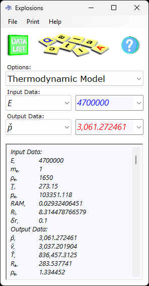
An example explosion event can be calculated using CalQlata's Explosion calculator, Fig 2:
See co-ordinates in Table 1 to the right of this page for the output listing from this calculation. As you can see, the deflagration index upper limit (Kₛ₂ < 500 bar-m/s) occurs 3-metres from the source, and the overpressure limit (pₒ < 10 barg) occurs 1-metre from the source.

Fig 2. Example Explosion Calculation
Example Calculation
from the PVRT formula; p = Rᵢ.ρ.Ṯ / RAM
1-metre from the source, where the temperature (Ṯ) is 2816.648 K;
the density of the gas 1-metre from the source may be calculated as follows;
ρ = p.RAM / Rᵢ.Ṯ = 1.20784 kg/m³
mass velocity through a primary vent (Fig 1) of 0.5m² may be calculated thus;
vₘ = ρ.v.A = 675.37 kg/s
and the time taken (0.00051 seconds) means that the mass of air shifted through the vent will be;
m = vₘ.t = 0.343 kg
The overpressure 1.05 metres from the source is 9.11 atm (<10 bar-g)
And the deflagration index 3.052 metres from the source is 490.6147( <500 bar-m/s)
Therefore, 3-metres is the minimum exclusion zone around the source.
Exclusion Zone
Exclusion zones are usually set to minimise the effects of overpressure on people or equipment in the immediate vicinity. Because it isn't practical to exclude flying objects, the exclusion zone is usually surrounded by a cage of suitable mesh size and strength to catch them.
If an acceptable overpressure at the limit of the exclusion zone is, say 0.1bar in the above calculation example, the exclusion zone (Fig 1) must be set to 5-metres from the source (see Table 1).

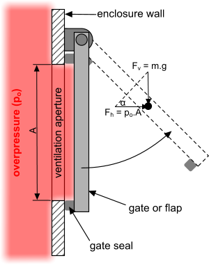
Fig 3. Ventilation Flap
Vents
A vent (or vents) should be located at such a distance that the overpressure is diffused as quickly as possible within the limits defined by the appropriate authority. There are a number of ways in which this can be achieved; blowout panels, valves, chimney stacks, etc.
Blowout panels may be made from weaker material than the enclosure wall, and/or held in place with shear bolts or edging. The problem here is that reinstatement will require substantial structural remedial work. Moreover, the flying panel may represent a danger to passers-by.
Valves tend to be applied to enclosures with limited volumes to diffuse, such as pipelines and accumulators.
Chimneys are normally used where exhausted gases must be contained, scrubbed or controlled. They can also be used if the enclosure may be permanently open to the atmosphere.
Where the enclosure must remain effectively airtight whilst holding a nominal overpressure to minimise atmospheric contamination, a sealed flap (Fig 3) may be used to accommodate occasional excess pressure. The mass of the flap will be set to lift only if the nominal overpressure is exceeded. Such a facility will automatically reset after use and requires no remedial work.
Primary & Secondary Vent Sizing
The principal objective of the primary flap-vent is to open - sufficient to leak - when the nominal overpressure is reached (or exceeded), such as when the seal is uncompressed, let's say, for example, rotating the flap by at least; α ≤ 0.3° and setting the vent area to; A = 0.5 m² (Fig 3).
For this to occur, the mass of the flap must be less than or equal to;
m ≤ p.a/g . Tan(α) ≤ 0.1bar . A/g . Tan(α) ≤ 10359.14431 . 0.5/9.80663139 . Tan(α) ≤ 2.765518877 kg
How much will the flap open at an overpressure of 964615.2376 N/m² (9.11 bar)?
α = atan(m.g / p.a) = Atan((2.765518877 x 9.80663139) ÷ (964615.2376 x 0.5)) = 0.003221773°
At the design overpressure - 1.05 metres from the source - the flap will rotate virtually to the horizontal. But as the internal overpressure falls, the flap will gradually close until the internal pressure is 0.1 bar above one-atmosphere; nominal overpressure.
Because the release of energy into an enclosed space - for any reason - along with the speed at which such energy travels, localised [reduced] overpressure may well occur within the enclosure away from the primary vent. It is for this reason that secondary vents (Fig 1) are usually incorporated in each enclosure wall.
However, where the release of pressurised gases, which may contain toxic matter within the enclosure, should be directed through the primary vent into a place of safety, the secondary vents may be designed to open at a predefined overpressure that will only allow the release of such gases in the event the enclosure structure would otherwise be threatened. Using the above calculation technique, you should design your secondary vent with smaller apertures or heavier flaps.
Notes
- NFPA provide free access to their relevant cosd Standard on Explosion Protection by Deflagration Venting for those wishing to view prior to purchase. Scroll down on the webpage to "View Free Access"
Further Reading
You will find further reading on this subject in reference publications(?)