Weld Strength Calculator
(fillet vs butt)

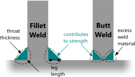
Fig 1. Weld Profiles
Whilst, there are innumerable alternative welding options (most of which are uniquely suited to particular applications), there are two general purpose methods that can be interchanged according to particular requirements (cost, time, access, procedures, etc.).
These are the fillet and butt welding methods, which can be applied to the end(s) of a beam, spar, column, etc., or in fact any part of a welded structure (Fig 1), the relative benefits of each may be listed as follows:
| Fillet Weld: | Butt Weld: |
|---|---|
| Quick Simple (preparation and procedures) Limited access (more suited to site welding) Cheap Less requirement for post-weld heat treatment Less chance of embrittlement |
Neater appearance Less weld metal Stronger Better fatigue resistance |
The thickness of all fillet welds is taken as the throat thickness in strength calculations. For volume calculations, the cross-sectional area of the weld is defined by the triangles in Fig 1 identified as; 'contributes to strength'. The excess material is not considered in the welding calculator's calculations as this will vary with the welder but will usually represent a pro-rata increase for the two methods.
Forces and Moments
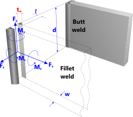
The forces and moments applied to the welded joint must follow the axes described in Fig 2 for the combined and equivalent stresses to be correct.
These can be calculated using CalQlata’s Beams, Beams+ or Bending Moments calculators.
Welding Calculator – Technical Help

Fig 2. Principle Axes
The welding calculator is designed to provide the user with the minimum amount of information (strength and weld material) to decide which weld type (fillet or butt) is best suited to his/her needs.
In the welding calculator ...
Combined Stress: refers to the mathematical combination of the shear stresses in a fillet weld, which must be less than half the yield stress of the weld material, including utilisation
Equivalent Stress: refers to the mathematical combination of the primary and shear stresses in a butt weld, which must be less than the yield stress of the weld material, including utilisation
Volume: Weld material volume refers to the volume of material enclosed within the triangular cross-sectional area identified in Fig 1 thus; 'contributes to strength'. Any given welder will generate an equivalent of excess material for either weld type. I.e. an additional 50% of excess material for one of his/her fillet welds is also likely to generate 50% excess in a butt weld. The excess weld material should be added to the material calculated in the welding calculator.
Units
You may use any units you like, but you must be consistent.
Common Input Data:
force (Fx); refers to a force (that may be positive or negative) along the x-axis
force (Fy); refers to a force (that may be positive or negative) along the y-axis
force (Fz); refers to a force (that may be positive or negative) along of the z-axis
moment (Mx); refers to a moment (that may be positive or negative) about the x-axis
moment (My); refers to a moment (that may be positive or negative) about the y-axis
moment (Mz); refers to a moment (that may be positive or negative) about the z-axis
Plate/Bar, RHS, THS & I/H Beam Input Data:
weld leg-length (ℓₒ); refers to the length of the weld as designated 'leg length' in Fig 1 and applies to the outside edges of the section being welded. Set this value to zero (ℓₒ=0) if the weld is to be omitted
weld leg-length (ℓᵢ); refers to the length of the weld as designated 'leg length' in Fig 1 and applies to the inside edges of the section being welded. Set this value to zero (ℓᵢ=0) if the weld is to be omitted (this input is ignored in the 'Irregular Shape' calculation option)
section width (w); refers to the width of the section being welded (parallel to the z-axis)
section depth (d); refers to the depth of the section being welded (parallel to the y-axis)
section material thickness (t₁); refers to the wall thickness of hollow sections and the flange thickness of I/H-Beams
section material thickness (t₂); refers to the web thickness of an I/H-Beam (this input is ignored in all other calculations)
Irregular Shape Input Data:
2ᴺᴰ area moment about y-axis (Iyy); refers to the second moment of area of the section (excluding weld) about the y-axis
2ᴺᴰ area moment about z-axis (Izz); refers to the second moment of area of the section (excluding weld) about the z-axis
cross-section area (A); refers to the cross-sectional area of the section (excluding weld)
max dim to outer edge 'y' (y); refers to the distance from the [unwelded] section’s neutral axis about the z-axis to the outer fibre in the y-direction
max dim to outer edge 'z' (z); refers to the distance from the [unwelded] section’s neutral axis about the y-axis to the outer fibre in the z-direction
2ᴺᴰ area moment about y-axis (Iyyₒ); refers to the second moment of area of the fillet weld pattern about the y-axis, using the throat thickness for the width of the weld
2ᴺᴰ area moment about z-axis (Izzₒ); refers to the second moment of area of the fillet weld pattern about the z-axis, using the throat thickness for the width of the weld
total length (Lₒ); refers to the total weld length (internal and external where applied)
leg-length (ℓₒ); refers to the 'leg length' of the weld as designated in Fig 1
Output Data:
weld throat thickness (twₒ); refers to the throat thickness of the outer fillet weld (Fig 1)
weld throat thickness (twᵢ); refers to the throat thickness of the inner fillet weld (Fig 1)
combined stress (σₑ); refers to the combined (shear) stress in the fillet weld(s)
{equivalent stress in the butt weld}
volume of weld metal (V); refers to the volume of material (bounded by the triangles designated 'contributes to strength' in Fig 1) in the fillet weld(s)
{volume of material in an equivalent butt weld}
Second Moment of Area of the Weld Pattern
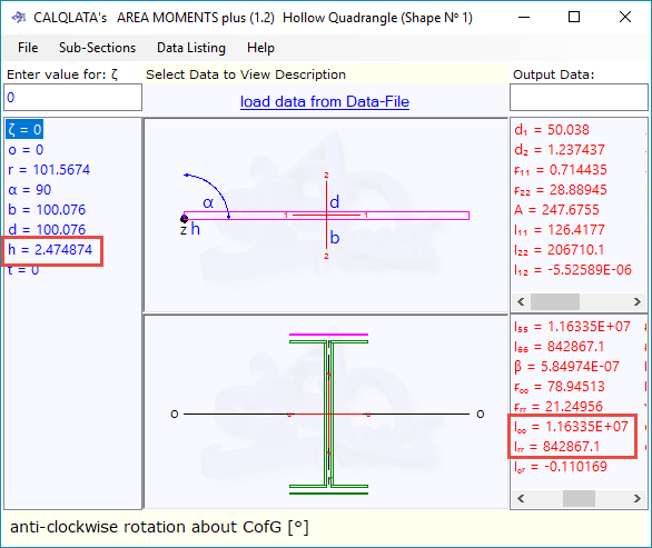
Fig 3 shows a calculation for the second moment of area of the weld pattern around an H-beam as calculated using CalQlata’s Area Moments+ calculator. You must to use the throat thickness of the weld for the width of each section.
The H-Beam fits within the weld pattern shown in the lower image of the Area Moments+ calculator.

Note: 'h' is entered as the weld throat thickness and Iₒₒ and Iᵣᵣ are the second moments of area about the z-z and y-y axes of the welding calculator respectively (Fig 1)
Applicability
Welding applies to any welded joint whereby a sectional shape is welded to a fixed and solid base. There is no limitation to the shape that can be calculated but, you will need to enter the second moments of area of the shape concerned and the weld pattern for irregular shapes, which can be calculated using CalQlata's Area Moments or Area Moments+ calculators or found in CalQlata's Steel Sections database.
Accuracy
Welding’s calculations are exact within the limitations described above and the integrity of the user’s input data and the quality of the weld(s).
Further Reading
You will find further reading on this subject in reference publications(56 & 57)

