Walls, Barriers & Tanks Calculator
All barriers are treated as walls in the following text.
The walls of tank may be treated as any other free-standing walls. The only difference being that at least three of its edges are fixed.
The Walls calculator may be then applied to each Tank wall individually.
Walls
Walls and barriers are normally subject to wind, waves or liquid weight dependent upon their protective or a containment nature.
The following conditions apply to the walls calculator:

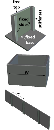
Fig 1. Typical Walls & Barriers
Edge Supports
The bottom edge of the wall or barrier is always fixed. The other three edges may be fixed or free to deform under load.
Edge stiffeners constitute the outer limits of the wall width or height, each of which requires a minimum rigidity (second moment of area) in order to prevent a specified displacement rate (δy[/ℓ]). The plate width is the horizontal distance between its vertical stiffeners or edges and its height is the vertical distance between its footings and its upper rim.
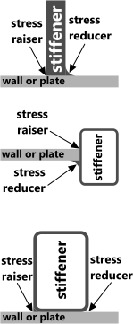
A stiffener can be:
a) significant wall thickening
b) a beam (or pillar)
or
c) a change in direction of the wall (e.g. a box)
Fig 1 shows some examples of a wall with 3 edges fixed.
Dimensions
A wall is rectangular with a dimensional ratio of 'width:height' that can be anything between 0 and 10
Materials
The material from which a wall is manufactured will determine its ability to resist an applied load, in terms of both stress and deflection. The variables that determine the properties of a material are its Poisson's ratio (ν) and its Young's modulus (E).
Protective Walls
A protective wall is a 2-D vertical plate intended to resist wind or water pressure that is equal all over its surface.
Containment Walls
A containment wall is a 2-D vertical plate intended to hold a liquid the full depth of its height. The pressure on the wall decreases linearly from a maximum value at its base to zero at the surface of the liquid, which is coincident with the top of the wall.
Properties of a Wall or Plate
The second moment of area of a unit width of a plate; I = t³÷12
The bending stress is therefore; σ = 6.M/t² (from M/I = σ/y)
Where: 't' is the plate thickness and 'M' is the bending moment due to the environmental load

Fig 2. Load
Conditions
Loading conditions
The loading conditions (Fig 2) considered in the walls calculator are as follows:
Uniform Load (wind or waves)
Air (wind) or water travelling at the wall at a constant speed.
The fluid force per unit area is the pressure (p)⁽¹⁾ you enter in the walls calculator for a 'uniform' loading condition. This pressure is assumed to be equal all over the face of the plate.
This loading condition can also be used to calculate the behaviour of a tank floor, or a panel thereof, using the '4 SIDES FIXED' calculation option.
Hydrostatic Load (liquid)
Containment of a static liquid at depth.
The force per unit area at the bottom of the wall is the density (ρ) of the liquid multiplied by its depth (h), which is assumed to be a maximum at the bottom of the wall and decreases linearly to zero at its surface (i.e. the top of the wall).
Walls Calculator – Technical Help
Assumptions for the walls calculator are as follows:
1) edge conditions are assumed to be fixed or free
2) edge conditions are consistent from top to bottom and full width
3) walls are assumed to be rectangular
4) wall thickness is constant
5) all walls are fixed at their base (along the bottom edge)
(For other conditions and configurations you should use CalQlata's SHEETS calculator)
Units
You may use any units you like, but you must be consistent.
Input Data
'h'; height, which is coincident with the top of the fluid in the hydrostatic loading condition
'W'; width of the wall between the edge stiffeners
't'; constant thickness of the wall or plate
'E'; tensile modulus of the wall or plate material
'δy'; permitted deflection per unit length of a stiffener
'p' [uniform loading condition]; pressure applied over the surface of the wall
or
'ρ' [hydrostatic loading condition]; density of the fluid contained by the wall
Output Data
'ω' [uniformly distributed load] total load per unit height applied across the width of the plate (maximum value for hydrostatic loading condition)
'σ̌' 'σ̌₁' & 'σ̌₂'; maximum bending stress in the plate
'σ̌ˣ' & 'σ̌ʸ' ; maximum horizontal and vertical bending stress in the plate respectively
'y̌'; maximum deflection in the plate
'z'; height to stress and deflection locations
'I' & 'I₁'; minimum second moment of area of vertical stiffener
'I₂'; minimum second moment of area of horizontal stiffener (4 SIDES FIXED only)
Stress Concentrations
Where present, a representative concentration factor⁽²⁾ should always be applied to edge stresses.
As large a radius as possible should be applied to surface changes between plate and stiffener in order to minimise stress concentrations. Fig 3 shows a number of methods for reducing stress raisers (concentrations).
To apply a stress concentration factor, you simply multiply the stress by the concentration factor, which is always greater than 1; i.e. σ = σ x F
Stiffeners

Fig 3. Typical Stiffeners
The walls calculator assumes that stiffeners are manufactured from the same material as the wall or plate, which is to be expected in any environment where water (or any other electrolyte) may be present, due to the potential for galvanic corrosion.
You may determine the sectional requirements for a stiffener, based upon the material used for the wall, by selecting an appropriate standard section⁽³⁾ or by calculation⁽⁴⁾
Applicability
The walls calculator applies to all rectangular walls and plates that are fixed at their base with one, two or all remaining sides constrained from significant movement in any direction.
The applicable loading conditions are:
a) uniform pressure all over the wall
and
b) hydrostatic pressure that decreases linearly with depth to zero pressure at the top edge of the plate
The walls calculator only applies to walls manufactured from a material that obeys Hooke's law under the applied load.
Accuracy
According to all the references used for this calculator, the expected error margin is between 7% and 15% dependent upon the height:width ratio. An additional margin of error is expected if modifications to the results are applied to accommodate variations in Poisson's ratio for the material⁽⁵⁾
When using the walls calculator for a final design sizing exercise, calQlata would recommend that the final result be multiplied by the following factors thus: σ = σ x (1 + (F-1) + Fᴾ + Fᴱ)⁽⁶⁾
Where;
F accommodates a stress concentration (>1)
Fᴾ accommodates varying Poisson's ratios (<1)
Fᴱ accommodates the expected error margin (<1)
Notes
- Wind speed can be converted to force per unit area using CalQlata's UNIQON calculator. Water in the form of current and/or waves can be converted to force per unit area using CalQlata's WAVES and FLUID FORCES calculators
- You can determine stress concentrations using CalQlata's STRESS CONCENTRATION calculator
- CalQlata's STEEL SECTIONS calculator
- CalQlata's AREA MOMENTS and AREA MOMENTS+ calculator
- The technical help page of the walls calculator provides guidance with respect to modification of the results to accommodate different materials (with different Poisson's ratio)
- It is considered over conservative to compound the factors by multiplying them together to generate a single factor as follows: σ = σ x (1 + F) x (1 + Fᴾ) x (1 + Fᴱ)
Further Reading
You will find further reading on this subject in reference publications(4 & 20)

