Bending Moment(s) and Shear Force(s) Calculator
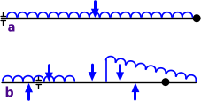
Fig 1. Simple & Complex loads
The calculation of shear forces and bending moments in a beam, with supports at each end, due to a single point load or a full-length uniformly distributed load is relatively simple (Fig 1a). But the same calculation for beams supported other than at its ends along with numerous point loads and/or variable (non-uniform) distributed loads can make this calculation a good deal more complicated (Fig 1b).
Shear Force Diagram
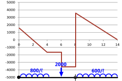
Fig 2. Shear Force Diagram
A shear force diagram is a graphical representation of the shear force variation along a beam as a result of a loading condition, the 'x-axis' being represented by the length of the beam and the 'y-axis' showing the shear force at any point along the beam.
If you divide the shear force at any point along the beam by its area at that point you will have calculated the shear stress in the beam due to that shear force
(τ = F ÷ A).
The shear force diagram for a typical complex beam loading condition is shown in Fig 2⁽¹⁾.
Bending Moment Diagram
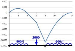
Fig 3. Bending Moment Diagram
A bending moment diagram is a graphical representation of the bending moment variation along a beam as a result of a loading condition, the 'x-axis' being represented by the length of the beam and the 'y-axis' showing the bending moment at any point along the beam.
If you divide the bending moment at any point along the beam by its section modulus at that point you will have calculated the maximum bending stress in the beam due to that bending moment
(σ = M ÷ Z).
The bending moment diagram shown in Fig 3 is for the same beam loading condition as that provided in Shear Force Diagram above⁽¹⁾.
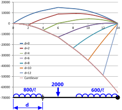
Fig 4. Support Positioning - Bending
Beam Supports
Bending moments and shear forces vary considerably with support positioning ('d') as can be seen in Figs 4 & 5. Where possible, supports should be positioned to minimise both conditions.
For example; the lowest bending moments for the loadcase identified in Fig 4 are achieved if the left-hand support is positioned at a distance about 4.0 from the left-hand end of the beam ('d=4'). Moreover, it can be seen from Fig 5 that the shear forces induced in the same beam by the same loading conditions are also at their lowest with the same support similarly positioned.
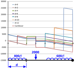
Fig 5. Support Positioning - Shear
The purpose of this calculation process is usually to minimise the size of your beam. If the supports are positioned correctly, the size of the beam may be reduced considerably.
For example, as can be seen in Fig 4, the difference in maximum and minimum bending moments for a beam with two supports is a factor of 10. That is, by correctly positioning your supports you can reduce the second moment of area of your beam by the same factor (10). A similar argument may also be applied to shear forces, where it can be seen in Fig 5 that you can reduce the cross sectional area of your beam by a factor of 5 with correct support positioning.
Bending Moments and Shear Forces Calculator
Technical Help
Units
You may use any units you like, but you must be consistent.
Sign Convention
You may apply positive loads up or down in this bending moment calculator, according to your preference but it is important that you are consistent with all applied loads.
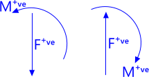
Fig 6. Sign Convention
If you direct positive forces upwards in the calculator, positive output bending moments will be in a clockwise direction. Should you apply positive forces downwards, however, positive bending moments will be reversed, i.e. anti-clockwise (Fig 6).
There is no sign convention for calculated shear forces as they are equal and opposite (in both directions) and induce no rotation.
Input Data
Beam Length ('L'): The length of your beam is the length that includes all applied loads and supports. Any length beyond all loads and supports will have no effect on bending moments or shear forces and therefore can be ignored.
Support Positioning ('dᴬ' & 'dᴮ'): In calculation option 'TWO SUPPORT' you may position supports 'A' and 'B' anywhere you like as long as support 'A' is always to the left of Support 'B'. Calculation option 'ONE SUPPORT' (cantilever) ignores any entered support positioning dimensions ('dᴬ' & 'dᴮ') and automatically fixes support 'B' at the right-hand end of your beam.
It is important to remember when switching between calculation options that the value entered for support 'B' in the 'TWO SUPPORT' calculation option will have been automatically reset to 'L' when switching to 'ONE SUPPORT' and will therefore need to be reset to the correct value when returning to 'TWO SUPPORT'
Point Loads ('F₀' to 'F₉' & 'd₀' to 'd₉'): You may enter your loads in any order (₀ to ₉) and you may mix positioning, i.e. it is not necessary to work from one end of the beam to the other in any particular direction.
Distributed Loads (w₀ to w₄ & d₀ to d₄): You may overlap these loads and enter them in any order (₀ to ₄) and you may mix positioning; i.e. it is not necessary to work from one end of the beam to the other in any particular direction, but you must ensure that dᴸ is less than dᴿ for all loads (w₀ to w₄).
Whilst these loads may be non-uniform (wᴸ ≠ wᴿ), both ends of distributed loads must be to the same side of the beam; i.e. you may not have one end of the uniform load positive with the other end negative; in other words -wᴸ and +wᴿ is not permissible.
Segments: This value ('seg') defines the accuracy (number of segments) in your shear force (Sx) and bending moment (Mx) co-ordinates, which can be used to ascertain the bending moment and/or shear force at discrete points anywhere along the beam or to plot your bending moment and shear force diagrams. This value may be set to any integer between 20 and 200 but will default to 50 if it is left blank or set to zero.
Output Data
Support Reactions ('Fᴬ' & 'Fᴮ'): These are the vertical loads applied to the respective support: 'Fᴬ' is the load applied to support 'A' and 'Fᴮ' is the load applied to support 'B'.
Maximum Shear Force ('F̌' & 'xᶠ'): This is the maximum shear force ('F̌') extracted from the shear force co-ordinates in the beam segments ('seg') along with its distance from the left-hand end of the beam ('xᶠ'). Therefore, the smaller your segments the more accurate this result will be.
Maximum Bending Moment ('M̌' & 'xᵐ'): This is the maximum bending moment ('M̌') extracted from the bending moment co-ordinates in the beam segments ('seg') along with its distance from the left-hand end of the beam ('xᵐ'). Therefore, the smaller your segments the more accurate this result will be.
Plotting Your Curves
(bending moment diagram and shear force diagram)
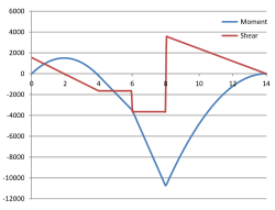
Fig 7. Curve Plotting
The procedure for plotting your curves in Microsoft's Excel spreadsheet is described in detail in the Catenary technical help page of this website. However, should you wish to plot the bending moments and shear forces on the same graph (Fig 7) you should select all three columns ('x', 'Mx' & 'Sx') including the headings, then plot using "Insert>"Chart>Scatter>Smooth Lines" (or "Straight Lines").
Accuracy
Whilst there is no error in any calculation or output result, apart from support reactions, which are exact at the support positions, the maximum bending moment ('M̌') and shear force ('F̌') are selected from the co-ordinate listings and may not be maximum values for the beam. Therefore, if you are looking for maximum accuracy for these values, you should set the segment lengths as small as possible ('seg=200').
However, it is unlikely that these maximum values will alter noticeably for 'seg' values greater than 50
Notes
- The example shear force and bending moment diagrams shown in Figs 2 & 3 have been calculated by MultiMoments and plotted in Microsoft's Excel spreadsheet using MultiMoments' co-ordinates. This loadcase is similar to example 4-6 & Figure 4-18 provided in reference (7).
- The bending moments calculated in this program can be converted into stress using CalQlata's Engineering Basics calculator.
Further Reading
You will find further reading on this subject in reference publications(1, 2, 3, 4 & 7)

