Pipe Flow Calculator
(API RP 14E criteria)
APIpe calculates the minimum internal diameter and wall thickness for a pipeline transporting single and multi-phase hydrocarbon fluids according to the recommended practice (API RP 14E; §18) issued by the offshore industry's most prominent authority: the API. APIpe calculates the performance criteria for liquids, gases and a combination of the two (2-phase fluid).
Whilst CalQlata's Pipe calculator focuses on the properties of the pipe itself and CalQlata's Pipe Flow focuses on the characteristics of the fluid passing through the pipe, APIpe concentrates on sizing the pipe for optimum average flow conditions. APIpe should be used first to obtain your pipe's diameter and wall thickness, followed by Pipe to determine final wall thickness (which should be at least equal to the wall thickness calculated here) with all additional loading conditions applied and then followed by Pipe Flow to determine the detailed characteristics of the fluid in the bore.
Liquid
Whilst a pure liquid could flow through a perfectly smooth [internal surface] pipeline with virtually no velocity constraints, most transported liquids naturally include entrained gas and/or solids within the liquid resulting in the need for velocity limitations to avoid erosion. Any liquid with entrained gas is a '2-phase' fluid. The trick is to know how much gas is in the pipe (see 2-Phase below).
If you are dealing with a pure liquid that fills its transportation pipeline and thereby excludes all gas, the only practical limitation to the fluid flow velocity is the possibility of the liquid heating due to frictional resistance between it and the pipe wall. For hydrocarbons, this could be a problem as the liquid exits the pipeline and becomes mixed with air (or another oxygenated gas) at which time the hot liquid could combust. In order to prevent this, API recommends that the liquid velocity should not exceed 15ft/s.
If you are dealing with a pure liquid that contains solids (e.g. sand), erosion will become a problem. The limiting flow velocity (ve) to avoid erosion is equal to the reciprocal of the square root of the compound density (ρ: liquid+solid) multiplied by a factor (F) between 100 (continuous operation) and 125 (intermittent operation): ve = F / √ρ
Gas
The principal flow limitation for a pure gas (devoid of all liquid) is an unacceptable pressure drop that may otherwise adversely affect the performance of in-line equipment. You can correct this problem by increasing the pipe's internal diameter.
Gases that contain a vapour or condensate are potentially erosive and must be treated as a 2-phase fluid.

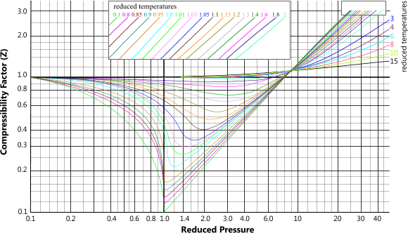
The gas compressibility factor ('Z') can be extracted from Fig 1, where;
Reduced Pressure = operating pressure ÷ critical pressure
Reduced Temperature = operating temperature ÷ critical temperature
The above formulas work equally well with metric or imperial units, however, do not forget that the pressure must exclude atmospheric pressure and the temperatures must be absolute (Kelvin or Rankine).
2-Phase
Minimum velocity for 2-phase lines should be 10ft/s to avoid slugging and separation (of gas and oil). To avoid erosion, a maximum velocity is recommended which will depend upon the gas:oil ratio (GOR).
Pipe Flow+ Calculator - Technical Help
Units
You may use any units you like, but you must be consistent.
Fluid Properties
The fluid properties: dynamic viscosity ('μ') and density ('ρ') for oil ('ᴼ') and gas ('ᴳ') must be entered in the 2-Phase calculation option. APIpe remembers the inputs as you change between calculation options (see Flow Rate below).
Flow Rate
As all entered data is remembered when you alter your calculation option (see Fluid Properties above) and the flow rate ('Q') is in different units for 'GAS' (10⁶ ft³/day) and 'OIL' or '2-PHASE' (bls/day), your results will be incorrect if the flow rate is not modified when switching to or from 'GAS'.
Pressure
The input pressure ('p') is the pressure at the inlet end of the pipe. The pressure drop ('δp') is the expected loss of pressure over the length of the pipeline as a result of friction between the fluid and the internal pipe wall and increases with inlet pressure.
Important Note: It is necessary to ensure that the input pressure is greater than the pressure drop.
Surface Roughness
Surface roughness ('ϵ'), i.e. the depth of surface irregularities, is applied in APIpe as a ratio of surface roughness to the inside diameter of the pipe (Ø). The accuracy of this property is important because it directly affects the Reynolds number of the moving fluid and therefore its operational acceptability.
The Moody fanning friction factor ('ƒ') is calculated using the Colebrook equation.
Wall Thickness
The wall thickness ('t') output from this calculator is based upon the recommended criteria in ANSI-ASME specification where 0.62 x SMYS is the maximum allowable stress in the pipe wall with a longitudinal weld factor of 1.0. If you require different acceptance criteria or you need to consider more complex loading conditions to the design pressure alone, you should use CalQlata's Pipe calculator.
Note that the wall thickness calculated in APIpe includes a minimum requirement for pressure strength plus the corrosion allowance ('a'). It does not, however, include the additional requirements for external loading conditions such as tension, torque and bending.
Further Reading
You will find further reading on this subject in reference publications(23)

